Basic Info.
Model NO.
oil trasnformer
Usage
Power Transformer
Frequency Characteristics
Power Frequency
Shape of Core
OD
Brand
Tongxun-Lianwei
The Rated Voltage
10/20/35kv
Frequency
50/60Hz
Tapping Range
+-2X2.5%
Insulation Grade
F
Local Discharge
<10PC
Insulation Level
10kv Li75AC35/AC3 20kv Li125AC55/AC3 35kv Li200
Noise Level
Jb/T10888 dB
Cooling Way
an/Af
Protection Grade
IP20
Short Circuit Capacity
GB1094.5
Mode of Operation
Operation Mode
Epoxy
Resin Insulated
Dry Type
Transformer
Resistance
Short Circuit
Strong Resistance
Weather
Transport Package
Export Wooden Packing
Specification
Oil immersed transformer
Trademark
TONGXUN-LIANWEI
Origin
Chongqing, China
HS Code
8504101000
Production Capacity
10000 Set/Year
Product Description
Our Quality systems are certified under ISO9001: 2015. Meanwhile, we strictly implement ISO14001: 2015 international quality and environmental management systems standards and ISO45001-2018 occupation health and safety management system standard.
MAIN PRODUCT
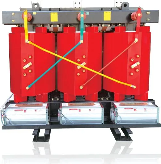
l SCB( 10, 11, 13)Series10-35kV 50~31500kVA Dry Type Transformer
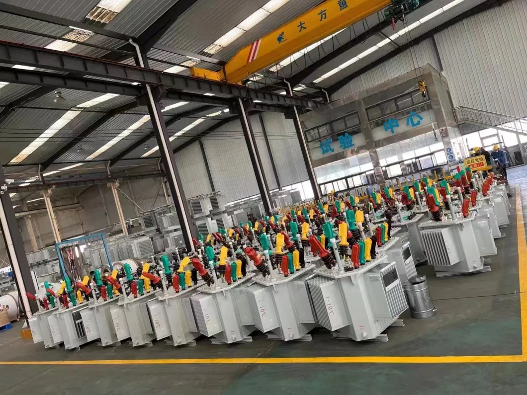
l S11/13 Series 10-35kV 50~31500kVA Oil Immersed Transformer
l S11/13 Series 30~35kV Oil Immersed Transformer( Side Outline Terminal)
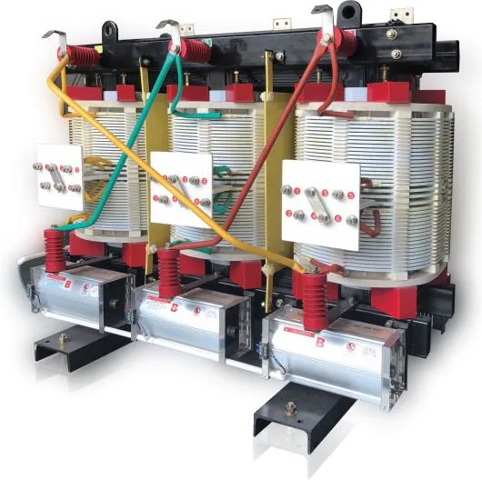
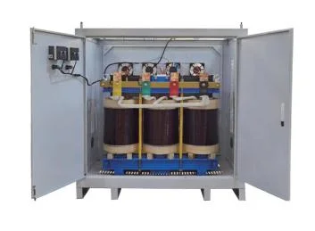
l SG(B) Series( H grade) 10-35kV 50~31500kVA Unencapsulateddry Type Transformer
l SZ11 Series 10-35kV 50~31500kVA Oil Transformer with OLTC (Main Power Transformer)
l YB Series 10kV 50~31500kVA Transformer Substation
l ZGS11 Series 10kV 50~31500kVA Box Type Transformer (American Style)
l High/Low Voltage Complete Sets of Equipment (Switchgear)
l Furnace Power Transformer
1. SCB( 10, 11, 13)Series10-35kV 50~31500kVA Dry Type Transformer
1. 1 Technical Parameters Note:All the dimension and weight is for reference only
Model | Rated capacity | Rated voltage | Connection | No-load loss | On-load loss | No-load current | Short circuit impedance | Dimension (L"W"H) | |
| HV | LV | 120ºC | |||||||
| (kVA) | (kV) | (kV) | (W) | (W) | (%) | (%) | (mm) | ||
| SC10-100/10 | 100 | 11 10.5 10 6.6 6.3 6 | 0.4 | Dyn11 Yyno | 400 | 1570 | 2.1 | 4 | 805'680*820 |
| SC10-125/10 | 125 | 470 | 1850 | 2 | 820'680'855 | ||||
| SC10-160/10 | 160 | 540 | 2130 | 2 | 820*680*890 | ||||
| SC10-200/10 | 200 | 620 | 2530 | 1.8 | 1010*900*990 | ||||
| SC10-250/10 | 250 | 720 | 2760 | 1.8 | 1040*900*1050 | ||||
| SC10-315/10 | 315 | 880 | 3470 | 1.6 | 1060*900*1180 | ||||
| SC10-400/10 | 400 | 970 | 3990 | 1.6 | 1120*1000*1180 | ||||
| SC10-500/10 | 500 | 1160 | 4880 | 1.6 | 1150*1000*1220 | ||||
| SCB10-630/10 | 630 | 1290 | 5880 | 1.4 | 1160*1000*1280 | ||||
| SCB10-630/10 | 630 | 1290 | 5960 | 1.4 | 6 | 1340*1000*1280 | |||
| SCB10-800/10 | 800 | 1520 | 6960 | 1.4 | 1390*1000*1290 | ||||
| SCB10-1000/10 | 1000 | 1760 | 8130 | 1.2 | 1450*1100*1350 | ||||
| SCB10-1250/10 | 1250 | 2080 | 9690 | 1.2 | 1480*1100*1450 | ||||
| SCB10-1600/10 | 1600 | 2440 | 11730 | 1.2 | 1510*1100*1590 | ||||
| SCB10-2000/10 | 2000 | 3050 | 14450 | 1.1 | 1790*1300*1600 | ||||
| 5CB10-2500/10 | 2500 | 3600 | 17170 | 1.1 | 1830*1300*1900 | ||||
2. S11/13 Series 10-35kV 50~31500kVA Oil Immersed Transformer

2. 2 Technical Parameters 10KV Note:All the dimension and weight is for reference only
Model | Ratedca pacity | Rated voltage | Connection | No - loadloss | On -load loss | No - loadcurre nt | meagv olag | Weight | Gauge( Crosswise " Lengthways) | Dimension ( L*W* H) | ||||
HV | Tapping range | LV | Transf ormer | Oil | Total | |||||||||
| ( kVA) | ( kV) | ( kV) | (W) | (W) | (%) | (%) | ( kg) | ( kg) | ( kg) | ( mm) | ( mm) | |||
| S11 - M ( R) - 30/ 10 | 30 | 6 6. 3 10 10. 5 11 | ±2* 2. 5% or ±5% | 0.4 | Dy n11 or Yy n0 | 100 | 630 | 2. 1 | 4 | 150 | 70 | 295 | 400*450 | 920* 680* 980 |
| S11 - M ( R) - 50/ 10 | 50 | 130 | 910 | 2.0 | 4 | 248 | 85 | 390 | 400*450 | 950* 720* 1020 | ||||
| S11 - M ( R) - 80/ 10 | 80 | 180 | 1310 | 1.8 | 4 | 335 | 105 | 515 | 400*450 | 1080* 720* 1100 | ||||
| S11 - M ( R) - 100/ 10 | 100 | 200 | 1580 | 1.6 | 4 | 360 | 115 | 560 | 550* 550 | 1100* 770* 1150 | ||||
| S11 - M ( R) - 125/ 10 | 125 | 240 | 1890 | 1. 5 | 4 | 380 | 135 | 630 | 550* 550 | 1120* 770* 1190 | ||||
| S11 - M ( R) - 160/ 10 | 160 | 270 | 2310 | 1.4 | 4 | 505 | 150 | 775 | 550* 550 | 1260* 780* 1220 | ||||
| S11 - M ( R) - 200/ 10 | 200 | 330 | 2730 | 1. 3 | 4 | 585 | 165 | 895 | 550* 550 | 1370* 695* 1345 | ||||
| S11 - M ( R) - 250/ 10 | 250 | 400 | 3200 | 1.2 | 4 | 715 | 205 | 1105 | 550* 550 | 1450* 765* 1365 | ||||
| S11 - M ( R) - 315/ 10 | 315 | 480 | 3830 | 1. 1 | 4 | 930 | 250 | 1350 | 550* 550 | 1460* 780* 1400 | ||||
| S11 - M ( R) -400/ 10 | 400 | 570 | 4520 | 1.0 | 4 | 980 | 290 | 1530 | 660* 660 | 1580* 880* 1470 | ||||
| S11 - M ( R) - 500/ 10 | 500 | 680 | 5410 | 1.0 | 4 | 1155 | 315 | 1755 | 660* 660 | 1640* 890* 1480 | ||||
| S11 - M ( R) - 630/ 10 | 630 | 810 | 6200 | 0.9 | 4. 5 | 1430 | 425 | 2195 | 660* 660 | 1680* 970* 1570 | ||||
| S11 - M ( R) - 800/ 10 | 800 | 980 | 7500 | 0.8 | 4. 5 | 1500 | 430 | 2400 | 820* 820 | 2030* 960* 1840 | ||||
| S11 - M ( R) - 1000/ 10 | 1000 | 1150 | 10300 | 0.7 | 4. 5 | 1700 | 500 | 2880 | 820* 820 | 2190* 1080* 1850 | ||||
| S11 - M ( R) - 1250/ 10 | 1250 | 1360 | 12000 | 0.6 | 4. 5 | 1970 | 640 | 3430 | 820* 820 | 2280* 1180* 1910 | ||||
| S11 - M ( R) - 1600/ 10 | 1600 | 1640 | 14500 | 0.6 | 4. 5 | 2500 | 740 | 4190 | 820* 820 | 2320* 1210* 1960 | ||||
| S11 - M ( R) - 2000/ 10 | 2000 | 1950 | 17400 | 0. 5 | 4. 5 | 3200 | 1200 | 5400 | 1070* 1070 | 2530* 1210* 2150 | ||||
| S11 - M ( R) - 2500/ 10 | 2500 | 2300 | 20240 | 0.4 | 4. 5 | 3800 | 1280 | 6510 | 1070* 1070 | 2280* 1920* 2360 | ||||
2. 2 Technical Parameters 35KV Note:All the dimension and weight is for reference only
Model | Rated Capacity | Rated Voltage | Connecti on | No-load cost | On-load cost | No-load current | Shortcircu it impedance | Weight | Gauge (Crosswise *Lengthways) | Dimension (L*W*H) | ||||
| High voltage | Tapping range | Low voltage | Untanking mass | Insulating oil weight | Gross | |||||||||
| (kVA) | (&) | H.V | (kV) | (W) | (W) | (%) | (%) | (kg) | (kg) | (kg) | (mm) | (mm) | ||
| Sll-50/35 | 50 | 35 38.5 | ±5% or ±2*2.5% | 0.4 | YynO or Dyn11 | 168 | 1210 | 2.00 | 6.5 | 290 | 285 | 710 | 620 | 1150*800*1650 |
| Sil-100/35 | 100 | 240 | 2075 | 1.80 | 420 | 380 | 1100 | 620 | 1310*1100*1780 | |||||
| Sil-125/35 | 125 | 272 | 2350 | 1.75 | 520 | 430 | 1380 | 620 | 1900*990*1800 | |||||
| Sil-160/35 | 160 | 290 | 2820 | 1.65 | 620 | 450 | 1460 | 620 | 1900*990*1900 | |||||
| Sll-200/35 | 200 | 345 | 3300 | 1.55 | 750 | 571 | 1700 | 620 | 1100*1000*2080 | |||||
| Sll-250/35 | 250 | 408 | 3900 | 1.40 | 780 | 585 | 1800 | 620 | 1910*1100*2080 | |||||
| Sll-315/35 | 315 | 488 | 4700 | 1.40 | 1030 | 640 | 2280 | 820 | 2200*1080*2120 | |||||
| Sll-400/35 | 400 | 585 | 5700 | 1.30 | 1100 | 660 | 2400 | 820 | 2250*1100*2150 | |||||
| Sll-500/35 | 500 | 690 | 6900 | 1.30 | 1240 | 840 | 2680 | 820 | 2250*1100*2200 | |||||
| Sll-630/35 | 630 | 832 | 7870 | 1.25 | 1300 | 880 | 2800 | 820 | 2280*1100*2200 | |||||
| Sll-800/35 | 800 | 985 | 9410 | 1.05 | 1820 | 860 | 3620 | 820 | 2450*1110*2350 | |||||
| Sil-1000/35 | 1000 | 1155 | 11545 | 1.00 | 2150 | 1020 | 4350 | 820 | 2480*1200*2450 | |||||
| Sil-1250/35 | 1250 | 1408 | 13940 | 0.85 | 2480 | 1120 | 4650 | 820 | 2480*1220*2540 | |||||
| Sil-1600/35 | 1600 | 1700 | 16700 | 0.75 | 2860 | 1300 | 5800 | 1070 | 2680*1400*2560 | |||||
| Sll-2000/35 | 2000 | 35 38.5 | ±5% or ±2*2.5% | 6.3 10.5 | Yd 11 | 2180 | 18380 | 0.75 | 6.5 | 2630 | 1270 | 5300 | 1070 | 2750*1600*2800 |
| Sll-2500/35 | 2500 | 2560 | 19670 | 0.75 | 3200 | 1400 | 6170 | 1070 | 2800*1800*3000 | |||||
| Sll-3150/35 | 3150 | 3040 | 23090 | 0.70 | 7 | 3780 | 1600 | 7100 | 1070 | 2800*2000*3100 | ||||
| Sll-4000/35 | 4000 | 3620 | 27360 | 0.70 | 4480 | 1840 | 8630 | 1070 | 2800*2100*3200 | |||||
| Sll-5000/35 | 5000 | 4320 | 31380 | 0.60 | 5400 | 2090 | 9950 | 1070 | 2860*2320*3510 | |||||
| Sll-6300/35 | 6300 | 5250 | 35060 | 0.60 | 7.5 | 6490 | 2380 | 11580 | 1070 | 3100*2410*3600 | ||||
| Sll-8000/35 | 8000 | 7200 | 38480 | 0.45 | 8500 | 3000 | 14700 | 1475 | 3400*3580*3750 | |||||
| Sil-10000/35 | 10000 | 8700 | 45320 | 0.45 | 10150 | 3200 | 15500 | 1475 | 3560*2700*3900 | |||||
| Sil-12500/35 | 12500 | 10080 | 53870 | 0.40 | 8 | 12600 | 3800 | 19200 | 1475 | 3560*3000*3890 | ||||
| Sil-16000/35 | 16000 | 12160 | 65840 | 0.40 | 15100 | 4800 | 22800 | 1475 | 4060*3300*3890 | |||||
| Sll-20000/35 | 20000 | 14400 | 79520 | 0.40 | 16800 | 5500 | 25600 | 1475 | 4100*3400*3960 | |||||
| Sll-25000/35 | 25000 | 16960 | 94050 | 0.35 | 21000 | 7100 | 30800 | 1475 | 4100*3400*3^80 | |||||
| Sll-31500/35 | 31500 | 20240 | 112860 | 0.35 | 24800 | 8000 | 36300 | 1475 | 4180*3500*3980 | |||||
3. SG(B) Series( H grade) 10-35kV 50~31500kVA Unencapsulateddry Type Transformer
3. 1 Technical Parameters Note:All the dimension and weight is for reference only
Model | Rated capacity | No-load loss | On-load loss (145ºC) | No-load current | Sound level | Short circuit impedance | Weight | Dimension (L*W*H) |
| (kVA) | (W) | (W) | (%) | (LPA)dB | (%) | (kg) | (mm) | |
| SG10-100/10 | 100 | 400 | 1690 | 1.7 | 65 | 4 | 600 | 930*1100*1150 |
| SG1C-200/10 | 200 | 620 | 2710 | 1.3 | 67 | 900 | 1000*1100*1360 | |
| SG10-315/10 | 315 | 380 | 3730 | 1.1 | 69 | 1350 | 1160*1100*1400 | |
| SG10-400/10 | 400 | 980 | 4280 | 1.1 | 69 | 1510 | 1230*1100*1355 | |
| SG10-500/10 | 500 | 1160 | 5230 | 1.1 | 70 | 1810 | 1350*1100*1570 | |
| SG10-630/10 | 630 | 1300 | 6400 | 0.9 | 71 | 6 | 1980 | 1350*1100*1520 |
| SG1C-800/10 | 800 | 1520 | 7460 | 0.9 | 72 | 2180 | 1490*1200*1530 | |
| SG10-1000/10 | 1000 | 1770 | 8760 | 0.9 | 72 | 2650 | 1560*1200*1700 | |
| SG10-1250/10 | 1250 | 2090 | 10370 | 0.9 | 74 | 3150 | 1580*1200*1640 | |
| SG10-1600/10 | 1600 | 2450 | 12580 | 0.9 | 75 | 3650 | 1650* 1200*1860 | |
| SG10-2000/10 | 2000 | 3050 | 15560 | 0.9 | 77 | 4280 | 1690*1500*2010 | |
| SG10-2500/10 | 2500 | 3600 | 18450 | 0.9 | 78 | 5210 | 1800*1500*2120 |
4. SZ11 Series 10-35kV 50~31500kVA Oil Transformer with OLTC (Main Power Transformer)
4. 1 Technical Parameters 10kV Note:All the dimension and weight is for reference only
Model | Rated Capacity | Rated Voltage | Conne ction | No- load cost | On-load cost | No- load curren t | Short- circuit imped ance | Weight | Gauge Crosswi se Length | Dimension (L*W*H) | ||||
HV | Tapping range | LV | Transfor mer | Oil | Total | |||||||||
| (kVA) | (kV) | H.V | (kV) | (W) | (W) | (%) | (%) | (kg) | (kg) | (kg) | (mm) | (mm) | ||
| SZ11-200/10 | 200 | 6 6.3 10 10.5 11 | ±5% Or ±2*2.5% | 0.4 | YynO or Dyn11 | 385 | 2910 | 1.6 | 4.0 | 645 | 185 | 980 | 550 | 1320*810*1300 |
| SZ11-250/10 | 250 | 450 | 3420 | 1.2 | 775 | 225 | 1180 | 550 | 1400*850*1270 | |||||
| SZ11-315/10 | 315 | 540 | 4105 | 1.1 | 100 | 260 | 1410 | 550 | 1470*870*1380 | |||||
| SZ11-400/10 | 400 | 640 | 4960 | 1.0 | 1040 | 310 | 1610 | 660 | 1570*930*1400 | |||||
| SZ11-500/10 | 500 | 770 | 5900 | 1.0 | 1195 | 320 | 1850 | 660 | 1620*940*1450 | |||||
| S211-630/10 | 630 | 960 | 7270 | 0.9 | 4.5 | 1480 | 440 | 2290 | 660 | 1700*1000*1510 | ||||
| S211-900/10 | 800 | 1120 | 9090 | 0.8 | 1560 | 450 | 2500 | 820 | 1830*1020*1580 | |||||
| SZ11-1000/10 | 1000 | 1360 | 10430 | 0.7 | 1760 | 520 | 2980 | 820 | 1930*1140*1640 | |||||
| SZ11-1250/10 | 1250 | 1560 | 12400 | 0.6 | 2030 | 660 | 3540 | 820 | 2030*1800*1680 | |||||
| SZ11-1600/10 | 1600 | 1920 | 14700 | 0.6 | 2580 | 740 | 4310 | 820 | 2170*1280*1740 | |||||
| SZ11-2000/10 | 2000 | 2050 | 17500 | 0.6 | 5.5 | 3300 | 1200 | 5500 | 1070 | 2480*1260*2220 | ||||
| SZ11-2500/10 | 2500 | 2500 | 21000 | 0.6 | 3900 | 1310 | 6630 | 1070 | 2530*1420*2400 | |||||
4. 1 Technical Parameters 35kV Note:All the dimension and weight is for reference only
Mode | Rated Capacit Y | Rated Voltage | Conne ction | No- load cost | On- load cost | No- load curren t | Short- circuit mpeda nce | Weight | Gaupe (Crosswise *Lengthwa ys) | Dimension (L*W+H) | ||||
HV | Tapping range | LV | Transfor mer | Oil | Total | |||||||||
| (kVA) | (kV) | H.V | (kV) | (W) | (W) | (M) | (%) | (kg) | (kg) | (kg) | (mm) | (mm) | ||
| SZ11-2000/35 | 2000 | 35 38.5 | ±3*2.5% Or ±4*2.5% Or ±13*1.25% | 63 10.5 | Yd11 | 2.30 | 19.24 | 1.00 | 6.5 | 2980 | 1470 | 5900 | 1070 | 2880*1650*2860 |
| SZ11-2500/35 | 2500 | 2.72 | 20.64 | 1.00 | 3600 | 1680 | 6780 | 1070 | 2920*1860*3050 | |||||
| SZ11-3150/35 | 3150 | 3.23 | 24.71 | 0.90 | 7 | 3830 | 1690 | 7900 | 1070 | 2920*2080*3160 | ||||
| SZ11-4000/35 | 4000 | 3.87 | 29.16 | 0.90 | 4780 | 1910 | 9330 | 1070 | 2930*2160*3250 | |||||
| SZ11-5000/35 | 5000 | 4.64 | 34.20 | 0.85 | 6010 | 2390 | 10800 | 1070 | 2960*2400*3580 | |||||
| SZ11-6300/35 | 6300 | 5.63 | 36.77 | 0.85 | 7.5 | 7100 | 2680 | 12250 | 1070 | 3260*2500*3700 | ||||
| S711-8000/35 | 8000 | Ynd11 | 7.87 | 40.61 | 0.75 | 8900 | 3100 | 15300 | 1475 | 3500*2620*3800 | ||||
| SZ11-10000/35 | 10000 | 9.28 | 48.05 | 0.75 | 10650 | 3500 | 16600 | 1475 | 3660*2730*3940 | |||||
| SZ11-12500/35 | 12500 | 1094 | 56.86 | 0.70 | 8 | 13000 | 4100 | 20300 | 1475 | 3680*3060*3940 | ||||
| SZ11-16000/35 | 16000 | 1317 | 70.32 | 0.50 | 15500 | 5060 | 23600 | 1475 | 4160*3350*3980 | |||||
| SZ11-20000/35 | 20000 | 15.57 | 82.78 | 0.50 | 17300 | 5800 | 24500 | 1475 | 4230*3500*4000 | |||||
5. YB Series 10kV 50~31500kVA Transformer Substation

5. 1 Technical Parameters Note:All the dimension and weight is for reference only
| High voltage unit(HV) | Low voltage unit(LV) | Transformer unit(T) | ||||||||
| Item | Unit | Data | Item | Unit | Data | Item | Unit | Data | ||
| Rated frequency | HZ | 50 | Rated voltage | V | 380/220 | Rated capacity | (kVAI | 30~2000 | ||
| Rated voltage | (kV) | 6 | 10 | 35 | Rated current of main circuit | A | 20~3000 | Short-circuit impedance | % | 4.0/4.5/6.5 |
| Maxworking voltage | (kV) | 6.9 | 11.5 | 40.5 | Rated short-time withstand current | kA | 15-30-50 | Tappingrange forHV | % | ±5 ±2*2.5 |
| Power frequency withstand voltage (P.E.on/close | (kV) | 32/36 | 42/48 | 95/118 | Rated peak withstand current | kA | 30-63-110 | Connection | Yyn0 or Dyn11 | |
| Lightning impulse withstand voltage (P-E,on/close | (kV) | 60/70 | 75/85 | 185/215 | Branch current | A | 10~800~1600 | |||
| Rated current | A | 400/630 | Branch circuit | 2-4-8-12 | ||||||
| Rated short-time withstand current | (kV) | 16(4S) | 20(2S) | Compensation capacity | kVar | 0~320 | ||||
| Rated peak withstand current | (kV) | 50 | ||||||||